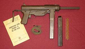
WWII era Guide Lamp M3 SMG with 30-round magazine and other accessories. The Buffalo Arms bolt in this original M3 is dated January 1944.
The M3 was an American .45-caliber submachine gun adopted for U.S. Army service on 12 Dec. 1942, as the United States Submachine Gun, Cal. .45, M3. The M3 was also a superior alternative to the Thompson submachine gun, as it was cheaper to produce, lighter, more accurate, and was also chambered on .45 ACP. The M3 was commonly referred to as the "Grease Gun" or simply "the Greaser", owing to its visual similarity to the mechanic's tool.
Intended as a replacement for the .45 caliber Thompson series of SMGs, the M3 and its improved successor, the M3A1 began to replace the Thompson in first-line service in late 1944 and early 1945. Due to delays caused by production issues and approved specification changes, the M3/M3A1 saw relatively little combat use in WWII.
History[]

M3 in use in Brittany, France, August 1944.
In 1941 the U.S. Army Ordnance Board observed the effectiveness of submachine guns employed in Western Europe, particularly the MP 40 and Sten guns, and initiated a study to develop its own Sten-type submachine gun in October 1942. The Ordnance Department requested the Army to submit a list of requirements for the new weapon and Ordnance in turn received a seperate list of requirements from both the Infantry and Cavalry branches for a shoulder-fired weapon with full- or semi-automatic fire capability in caliber .45 ACP or .30 Carbine. The two lists of requirements received by Ordnance were then reviewed and amended by officials at Aberdeen Proving ground. The amended requirement called for an all-metal weapon of sheet metal construction in .45 ACP caliber, designed for fast and inexpensive productiion with a minimum of machining, and featuring a dual auto and semi-automatic fire capability, a heavy bolt to keep the cyclic rate under 500 rpm, and the ability to place 90 percent of all shots fired from a standing position in full-automatic mode on a 6x6 foot target at a range of 50 yds. The benchmark for testing the M3's performance would be the M1928A1 Thompson.
George Hyde of General Motor's Inland Division was given the task of designing the new weapon, while Frederick Samson, Inland Division's chief engineer, was responsible for preparing and organizing tooling for production. The original T15 specifications of 8 Oct. 1942 were altered to remove a semi-auto fire function, as well as to permint installation of a kit to convert the weapon's original .45 caliber to that of 9mm Parabellum. The new designation for the 9mm/.45 full-auto only weapon was the T20. Five prototype models of the .45 T20 and five 9mm conversion kits were built by General Motors for testing. At the initial military trials, the T20 successfully completed its accuracy trials with a score of 97 out of 100. In the endurance test, the test weapon fired more than 5,000 rounds of brass-case ammunition, with only two failures to feed. For Army test boards composed of multiple Army service branches independantly tested and reviewed the T20 prototype weapons including the Airborne Command, the Amphibious Warfare board, the Infantry Board, and the Armored Forces Board. All four branches reported malfunctions caused by the M3 magazine, mostly attributed to defective or jammed magazine followers.
The T20 was formally approved by U.S. Army ordnance for production at GM's Guide Lamp Division in Anderson, Indiana in Dec. 1942 as the U.S. Submachine Gun, Caliber .45, M3. Guide Lamp produced 606,694 of the M3 variant submachine gun between 1943 and 1945. Although reports of malfunctions casued by the single-feed magazine design appeared during the initial firing trials, no changes were made to the M3 magazine.
With its stamped, riveted, and welded construction, the M3 was originally designed as a minimum-cost small arm, to be used and discarded once it became inoperative. As such, replacement parts, weapon-specific tools and sub assemblies were not made to ordnance level commands at the time of the M3's introduction to service. In 1944, a shortage of M3 SMGs created by interim production changes forced U.S. Army Ordnance workshops to fabricate pawl springs and other parts to keep existing weapons operational.
After its introduction to service, reports of unserviceability of the M3 commenced in February 1944 with stateside units in training, who reported early failure of the cocking handle/bolt retraction mechanism on some weapons. Similar reports came into Ordnance from U.S. forces in Britain who were issued the M3. An investigation revealed several dificiencies in the construction of some M3's bolt retraction mechanism, together with issues concerning barrel removement and retention as well as easily bent rear sights. As a result, several product improvemetns were incorporated into all new M3 production, including a new design retracting pawl with improved heat treatment, a new spring stop fitted to the sides of the fixed "L" rear sight. After new complaints were raisted about accidental magazine releases and failure of the wire buttstock to remain in place in the collapsed position, two additional changes were made to M3 production and approved by Ordnance on 31 Aug. 1944. This included a small sheetmetal guard around the magazine release button, and the inclusion of a stop between the two rods forming the wire stock at the butt end.
In Dec. 1944, in response to field requests for further developments to the basic M3 design, an improved, simplified variant of the M3 was introduced, the M3A1. 15,469 M3A1 submachine guns were produced before the end of WWII.
It was originally hoped that the M3 could be produced in numbers sufficient to cancel future orders for the Thompson submachingun, and allow to the Army to gradually withdraw the latter from front-line service. However, due to unforeseen production delays and requests for modifications, the M3 never replaced the Thompson during WWII, and purchases of the Thompson continued until Feb. 1944. A total of 622,163 M3/M3A1 submachine guns of all types were assembled by the end of World War II, by which time the Thompson, at over 1.5 million guns produced, outnumbered the M3 and M3A1 in service by a factor of nearly three to one.
Design details[]
The M3 was an automatic, air-cooled blowback-operated weapon that fired from an open bolt. Constructed of plain .060-in thick sheet steel, the M3 receiver was stamped in two halves that were then welded together. The M3 was striker fired, with a fixed firing pin contained inside the bolt. The bolt was drilled longitudinally to support two parallel guide rods, upon which were mounted twin return (recoil) springs. This configuration allowed for larger machining tolerances while providing operating clearance in the event of dust, sand, or mud ingress. The M3 featured a spring-loaded extractor which was housed inside the bolt head, while the ejector was located in the trigger group. Like the British Sten, time and expense was saved by cold-swaging the M3's barrel.
Operating mechanism[]
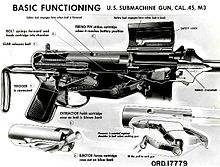
A diagram of the M3 illustrating function.
The M3 operating sequence is as follows: the bolt is cocked to the rear using the cocking handle located on the right side of the ejector housing. When the trigger is pulled, the bolt is driven forward by the recoil springs, stripping a round from the feed lips of the magazine and guiding the round into the chamber. The bolt then continues forward and the firing pin strikes the cartridge primer, igniting the round, resulting in a high-pressure impulse, forcing the bolt back against the resistance of the recoil springs and the inertial mass of the bolt. By the time the bolt and empty casing have moved far enough to the rear to open the chamber, the bullet has left the barrel and pressure in the barrel has dropped to a safe level. the M3's comparatively low cyclic rate of fire was a function of the relatively low pressure generatied by the .45 ACP round, a heavy bolt, and recoil springs with a lighter-than-normal compression rate.
Features[]

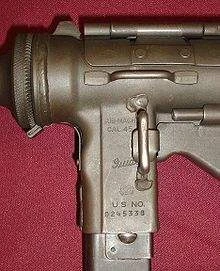
M3 receiver markings.
The gun used metal stamping and pressing, spot welding, and welding extensively in its construction, reducing the number of man-hours required to assemble a unit. Only the barrel, bolt and firing mechanism were precision machined. The receiver consisted of two sheet metal halves welded together to form a cylinder. At the front end was a knurled metal cap which was used to retain the removable barrel. The cold-swaged, rifled barrel had 4 right-hand grooves. M3 and M3A1 submachine guns could be fitted with an optional, detachable flash hider, though none saw service in WWII. A later production flash hider designated Hider, Flash M9 was produced in time to see service during the Korean War. It proved popular in combat, as freqent night engagements emphasized the need to reduce flash signatures on small arms. In Korea, U.S. soldiers equipped with automatic weapons were taught to look above the flash of their weapon during night firing, a tactic that sometimes prevented the detection of crawling enemy infiltrators and sappers.
Projecting to the rear was a one-piece wire stock made from a formed steel rod that telescoped into tubes on both sides of the receiver. Both sides of the stock were tapped and drilled so that it could be used as a cleaning rod. It could also be used as a disassembly tool or as a wrench used to unscrew the barrel cap.
The M3's cocking handle assembly was located on the right-hand side of the receiver on the ejector housing, just forward and above the trigger, and consisted of nine parts. As the handle was pulled to the rear, a pawl rises to engage a notch in the bottom of the bolt, pushing the bolt to the rear until it locked back on the sear.
The fixed sights consisted of a rear apeture sight preset for firing at 100 yds and a front blade foresight. All M3 submachine guns were test-fired for accuracy at a distance of 100 ft. With the sights ste at six-o'clock on a bullseye target, each gun was required to keep four out of five shots within or cut the ege of a three-inch bulls' eye to meet accuracy requirements.
The weapon's only safety was the hinged ejection port dust cover. This cover had a projection on the underside that engaged a notch on the bolt, locking the latter in its forward and rearmost positions. The M3 had no mechanical means of disabling the trigger, and the insertion of a loaded magazine would load the gun. With receiver walls made of relatively thin-guage sheet metal, the M3/M3A1 were subject to disabling damage of dropped on an open dust cover-the covers bent easily, negating the safety feature. Dropping the gun on a sharp or hard surface could dent the receiver enough to bind the bolt.
The M3/M3A1's 30-round magazine was the source of complaint throughout its service life. Unlike the Thompson, the M3 fed from a double-column, single-feed detachable box magazine which held 30 rounds and was patterened after the Sten magazine; the single feed design proved difficult to load by hand, and was more easily jammed by mud, dust, and dirt than double-column, double-feed designs like the Thompson. Additionally, the feed lips of the single feed design proved more susceptible to feed malfunctions when slightly bent or damaged. Plastic dust caps were later issued to cover the feed end of the magazine and keep out dust as well as protect the sensitive feed lips.
Variants[]
M3A1[]
In Dec. 1944 a modernized version of the M3 was introduced into service known as the M3A1, with all parts except the bolt, housing assembly, and receiver interchangeable with those of the M3. The M3A1 had several improvements, the most significatn was the elimination of the troublesome crank-type cocking lever assembly, replaced by a recessed cocking slot machined into the top front portion of the bolt, allowing it to be cocked by inserting a finger into the cocking slot and pulling back the bolt. The retracting pawl was removed, and a clearance slot for the cover hinge rivets was added. The ejection port and its cover were lengthened to allow the bolt to be drawn back far enough to be engaged by the sear, and the safety lock was also moved further to the rear on the cover. To facilitate loading the single-feed magazine, a magazine loading tool was welded to the wire stock; it also served as a cleaning rod stop. The barrel bushing received two flat cuts that assisted in barrel removal by using the stock as a wrench. The barrel rachet itself was redesigned to provide a longer depressing level for easier disengagement from the barrel collar. Furthermore, the spare lubricant clip (located on the left side of the cocking lever assembly) was removed, replaced with an oil reservoir and an oiler in the pistol grip of the receiver assembly. The stylus on the oiler cap could also double as a drift to remove the extractor pin. At 7.95 lbs empty, the M3A1 was slightly lighter than the M3, at 8.15lbs empty, primarily due to the simplified cocking mechanism. The M3A1 was formally approved for production on 21 Dec. 1944.
The M3A1 modifications resulted in a submachine gun with reduced weight and improved reliability, improved maintenance, and easier field stripping (the original M3 required removal of the trigger guard and detachment of the cocking crank assembly from the receiver housing before unscrewing the barrel, whereas the M3A1 required the user to merely unscrew the barrel). To date, only one 9mm conversion kit for the M3A1 has been discovered.
Because it had already been issued in large numbers, the existing M3 magazine design was retained despite demonstrated dificiencies exposed during the weapon's firing trials and its early combat service. In an effort to improve reliability, a hard plastic Tenite cap designated T2 was adopted in Nov. 1944 to fit over the feed lips of loaded magazines. These caps protected the feed lips while keeping out dirt, sand, and debris. Sometime during the 1960s the hard plastic T2 cap was replaced in service with one of pliant neoprene rubber, which could be removed with less noise. Unfortunately, during service in the humid climate of Vietnam it was discovered that the rubber cap caused rust to form on the covered portion of the magazine, while causing loaded ammunition to corrode.
Initially, existing M3 submachine guns entering Ordnance facilities for repair were not upgraded to M3A1 standard, but merely inspected to ensure they had the improved M3 housing assembly and magazine release shield. During the Korean War, existing M3 guns in service were converted to the improved M3A1 configuration using additional new production parts. During the conversion, armorer frequently removed the M3 cocking handle, leaving the rest of the now-redundant cocking mechanism inside the subframe. Overall, the M3A1 was seen by most most soldiers and Ordnance technicians as an improvement over the M3. However, complaints of accidental discharge continued to occur even as late as the Korean War. These incidents were sometimes caused by dropping the weapon on a hard surface with an impact sufficient enough to knock open the ejection port cover and propel the bolt backwards (but not enough to catch the sear). The return springs would then propel the bolt forward to pick up a cartridge from the magazine and carry it into the chamber, where the bolt's fixed firing pin stuck the primer upon contact.
The M3 and M3A1 were largely withdrawn from U.S. frontline service in 1957, but continued to be used until the mid-1990s by armored vehicle crews and truck drivers. During the 1991 Gulf War, drivers of the 19th Engineer Battalion attached to the First Armored Division were equipped with the M3A1 as part of their vehicle TOE.
Foreign variants[]


Philppine Naval Special Warfare Group members conduct interdiction training with the U.S. Coast Guard in Cebu city, 2009. Two of them are armed with M3s.
In 1954, a variant of the U.S. M3A1 submachine gun was designed at the Argentine FMAP (Fabrica Militar de Armas Portatiles) factory in the city of Rosario and put into production the following year as the P.A.M.1 (Pistola Ametrelladora Modelo 1). Constructed of somewhat thinner-guage steel than the U.S. M3A1, the P.A.M.1 was in essence a 7/8-scale replica of the U.S. weapon in 9mm Parabellum caliber, but was lighter and had a higher rate of fire. In service, the P.A.M.1's thinner receiver tended to overheat with extended firing, while the gun itself proved somewhat more difficult to control in automatic fire despite the smaller caliber. Additionally, triggering the weapon to fire individual shots proved difficult owing to the increased rate of fire. Problems with accidental discharges and accuracy with the P.A.M.1 led to an improved selective-fire version with a grip safety on the magazine housing known as the P.A.M.2, first introduced in 1963. Colloquially reffered to as La Engrasadora (the Greaser), 47,688 P.A.M.1 and P.A.M.2 submachine guns were produced between 1955 and 1972. A number of P.A.M.1 and P.A.M.2 submachine guns were used by the Argentine Army during the Falklands Islands War with Great Britain in 1982, and captured examples were tested by UK military forces.